 |
|---|
 |
 |
 |
 |
 |
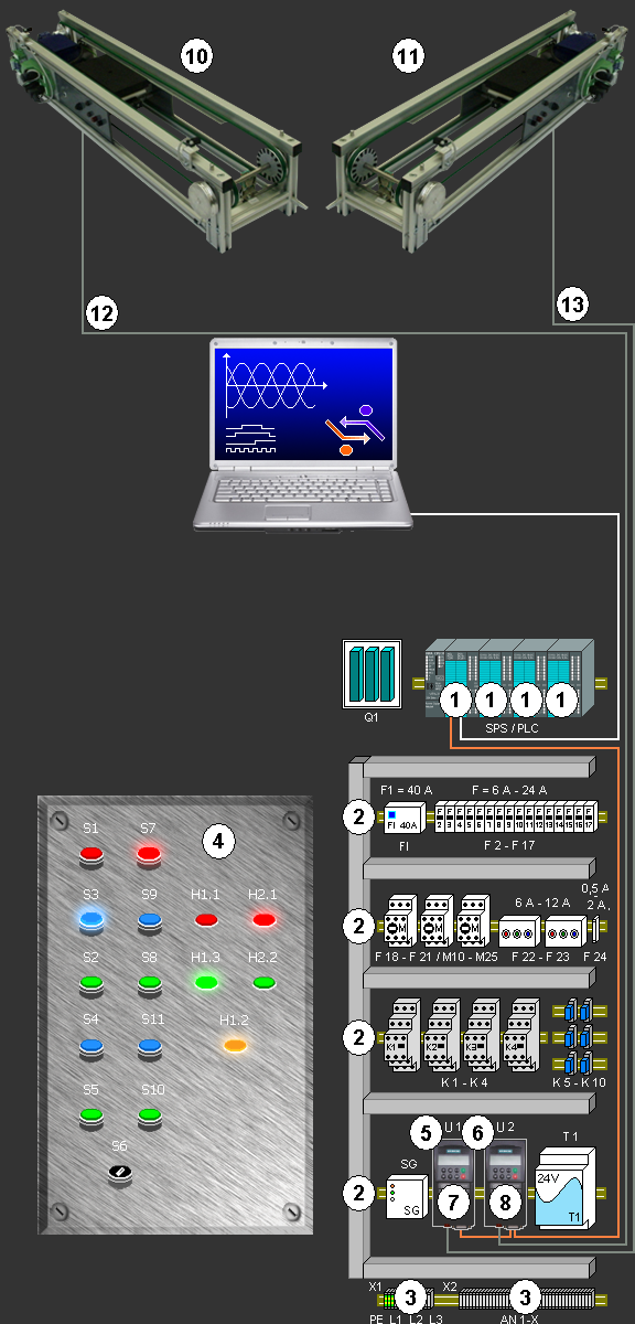
4.4 Setup Description of the System
01. Provision and visual inspection of the individual components.
02. Wiring at the PLC, rack, terminal, and control panel (Position 1, 2, 3 & 4).
03. Plug in the PROFIBUS communication module (Position 5 & 6).
04. Secure PROFIBUS DP with connectors and network with PLC and Micromaster
(Position 7, 8 & 1).
05. Connect USB cable to the PLC and PG (Position 9 & 1).
06. Provide power from the Micromaster to the conveyor (Position 10, 11, 12, 13, 7 & 8).
07. Parameterize the Micromaster 420 (Position 7 & 8).
08. Write program on the PG and transfer to the PLC (Position 9 & 1).
09. Input test via PG at the control panel and PLC (Position 9, 4 & 1).
10. Output test via PG at the control panel and PLC (Position 9, 4 & 1).
11. Function test.