 |
|---|
 |
 |
 |
 |
 |
4.3 Short Description Profibus DP, Cable, Connector
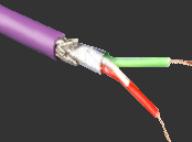
Profibus DP cable according to DIN 19245
Construction: Conductor: single-core bare copper Ø 0.64 mm
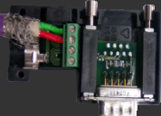
- 1st wire red, 2nd wire green, each with 1 dummy wire, twisted in pairs9-pin SUB-D connector housing, 90° angled for direct
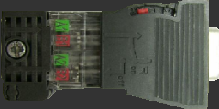
connection to the PLC.9-pin SUB-D connector housing for networking individual stations.
PROFIBUS-DP (Process Field Bus Decentralized Periphery) is designed for efficient data exchange
at the field level. Here, central automation devices such as
PLC/PC communicate via a fast serial connection with decentralized field devices like drives, valves
and frequency inverters. Process data transmission occurs cyclically. PROFIBUS is set up in a
line structure (up to 32 participants possible). The ends of the lines must be equipped with a
termination resistor. Profibus data is transmitted via a 2-wire shielded
twisted pair cable using RS485 physical layer. Each bus participant has a pull-down resistor on the DATA-A line
and a pull-up resistor on DATA-B, each 390?. The two end participants must have the termination resistor between DATA-A and DATA-B (220?) activated. The resistors are integrated into the connectors. The cable length in one
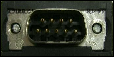
bus segment can be 400 m (500 kbit/s) and 100 m (12 Mbit/s). 9-pin D-SUB connectors are used.
Main Technical Features of Profibus Connector:
Baud rate: 9.6 kbit/s ... 12 Mbit/s
Interface: 9-pin SUB-D
Power supply: +5 Volt from Profibus device
Current consumption: 5.5 mA
Operating temperature: 0 ... +60° C
Storage temperature: -25 ... +80° C
Relative humidity: Max. 75% at 25° C
Protection class: IP40
Bus termination: switchablePin assignment of 9-pin D-Sub connector
Data line A [RxD/TxD-N] (8)
Data line B [RxD/TxD-P] (3)
Shield (1)
DGnd (5)
VP +5V (6)
Electrical Properties of the Cable:
Operating voltage (peak voltage): * 100 V
Test voltage: 3,600 V, DC 3 sec
Operating temperature: -40°C to +60°C
Bending diameter: > 150 mm
Other Required Interfaces
MPI/DP for communication with the PLC and PG.
USB for communication with the PLC and PG.