 |
|---|
 |
 |
 |
 |
 |
5.1 Hardware Configuration
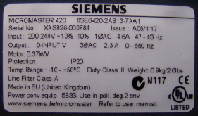
Label of a Micromaster 420, technical data for identification, information, and configuration.
The hardware configuration is carried out in the Step 7 program V.5.3.
This configuration is necessary so that components and the CPU of the PLC
can communicate flawlessly with the Micromaster 420 via the PROFIBUS-DP network.
The configuration is performed via a grid structured like a shelf (table).
The necessary components can be retrieved from a hardware catalog integrated in the program.
Configuring the individual components requires multiple details:
model number, order number, and technical data of the components must be specified,
which can be found in the manual or on labels attached to the devices
or directly printed on the devices. If the required components are not listed in the catalog,
they can be installed using a GSD (Device System File), usually provided by the manufacturer
on CD or diskette. After completing the configuration, a hardware address must be assigned.
This ensures that all connected devices can be properly identified and addressed by the CPU.
The following table provides information about the configuration.Components to be Configured
PS307 2A 24V DC
Model no.: 307-1BA00-0AA0
(S7 Power Supply)
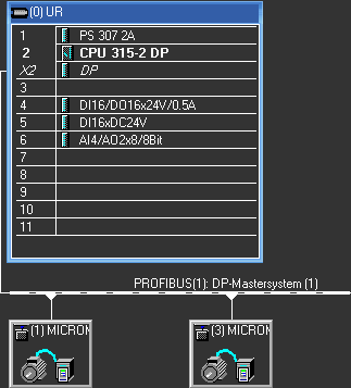
Excerpt from the Step 7 hardware configuration program
Simatic S7-300
CPU315-2 DP
Model no.: 315-2AF03-0AB0
(PLC)
SM323 DI 16/DO16 x DC24V
Model no.: 323-1BL00-0AA0
(Digital Input/Output Module)
SM321 DI 16 x DC24V
Model no.: 321-1BH02-0AA0
(Digital Input Module)
SM322 DO 8 x REL. AC230V
Model no.: 322-1HF01-0AA0
SM334 AI4/AO2 x 8BIT
Model no.: 334-0CE01-0AA0
(Analog Input/Output Module)
2 x Micromaster 420
0 HP, 2PZD (PPO 3)
Address No.1: Range 256.259
Address No.3: Range 260.263