6.0 Security
Implementing technical security measures in such a system is by far the most challenging part of the project. Not only in application, but even more in development, it can be a never-ending nightmare. Cybercriminals’ tricks are becoming increasingly sophisticated. For example, a DDoS attack is a distributed denial-of-service attack that can block multiple systems. IT infrastructures are deliberately overloaded, which can even paralyze the Internet. Cybercriminals can take down web-based systems of companies or their websites, causing major financial damage.
While it is not strictly necessary for this project to design a security concept operating across all seven layers of the Internet, we include it for completeness and to better understand functionality, as it may be applied in other projects or enterprises. All Internet transmission technology is based on the seven OSI layers.
Here is a brief overview of the ISO/OSI reference model:
- Layer 1 - Physical Layer
- Layer 2 - Data Link Layer
- Layer 3 - Network Layer
- Layer 4 - Transport Layer
- Layer 5 - Session Layer
- Layer 6 - Presentation Layer
- Layer 7 - Application Layer
Even a firewall operating across all seven layers may not fully stop a DDoS attack, but it can mitigate its effects at certain levels. Additional measures are required for complete protection.
Security should operate across all layers, so we implement protection on all seven layers. Layer 1 is the most difficult to control, while Layer 7 is the hardest to filter. Anyone familiar with iptables understands the complexity and appreciates a well-configured firewall distribution.
Brief overview:
Layer 1 is secured via switches. Physical interfaces are mechanically protected, CAT-5 cables are assigned to specific ports, and wireless technologies are not used.
Layer 2 is secured via ARP (Address Resolution Protocol). Each MAC address is assigned to local devices. Unregistered devices cannot communicate.
Layer 3 is secured with a NAT gateway. Devices belonging to the infrastructure are statically assigned, with routing tables defined and protocol standards set.
Layer 4 is secured via packet filtering. All IP addresses and protocol standards (TCP/IP, UDP) are statically defined. All outgoing and incoming ports are blocked (drop). Connection states are logged and adapted to required code bits (ack, syn, fin, urg, psh, rst).
Layer 5 is separated from the network via Socks5 and Socks4a, with all transmissions routed through a designated port.
Layer 6 is secured with SSL/TLS encryption and tunneling.
Layer 7 is secured via DPI/IDS/IPS, blocking unused applications, monitored through Snort or Layer 7 filters on pfSense/RouterOS.
This security plan was designed for the local system only.
On the remote server, filtering is limited to Layers 3–7, as access to devices is restricted to administrators. Therefore, the firewall concept is reduced to standard Layers 3–4.
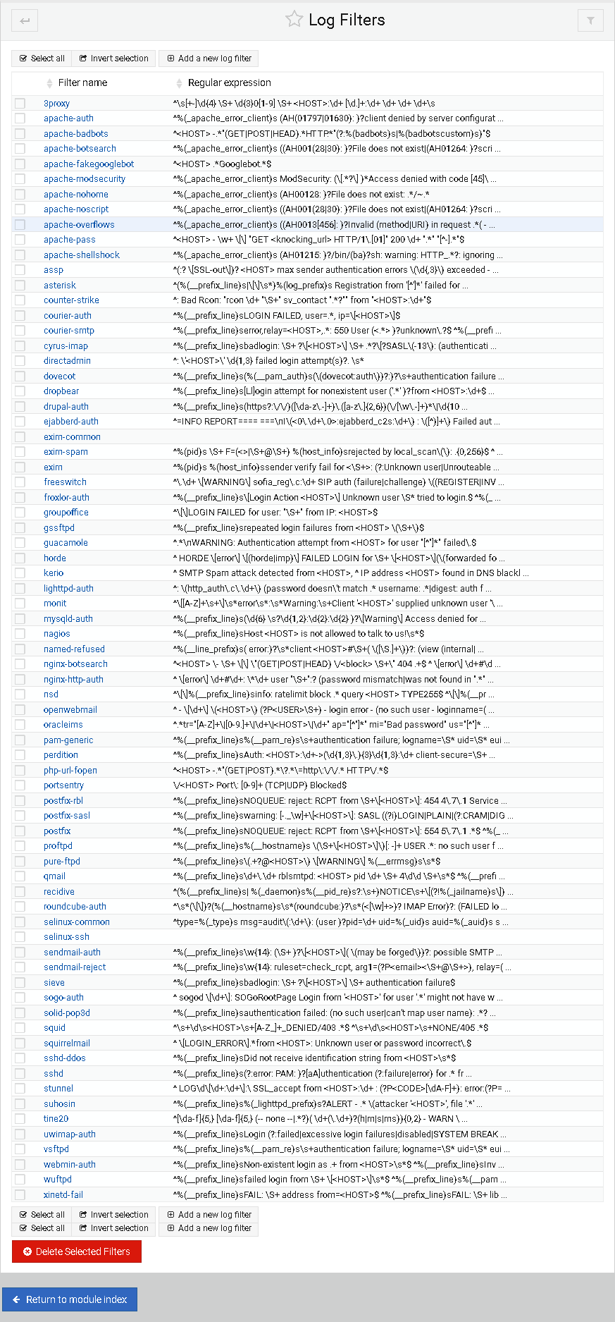
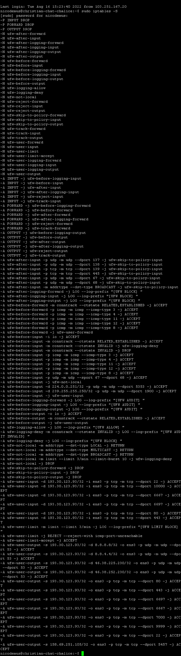
Fail2Ban is used on the server along with a custom iptables rule set, which is similar to the packet filter rules on pfSense and RouterOS.
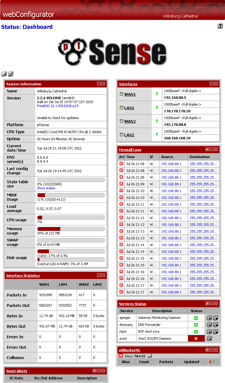
pfSense Dashboard
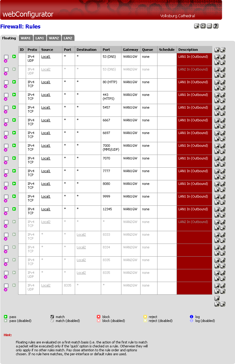
pfSense Packet Filter
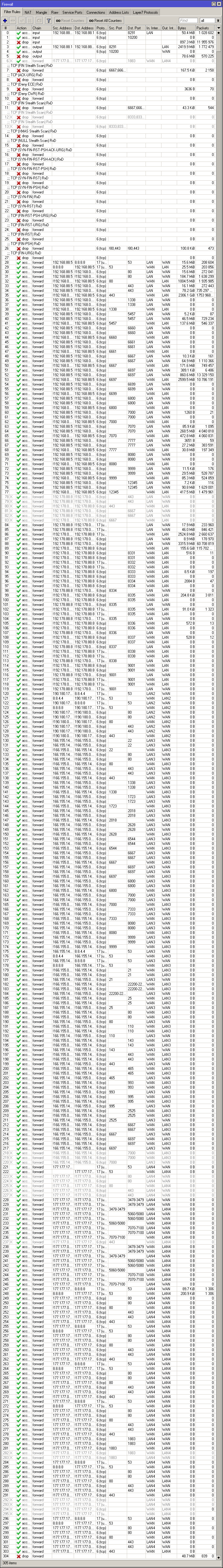
RouterOS Packet Filter
Some screenshots of internal filter settings on the remote system.
iptables Rules
Fail2Ban Log Filter in Webmin